
Mechanical Layer Pair机械相对层设置
参考官网
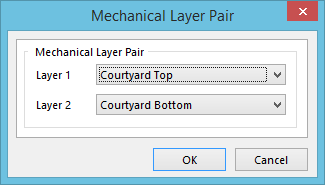
该功能允许将Layer1和Layer2设置为相对层,这样将对元器件进行镜像操作时,元器件的相关图形也会做层面的改变(参考内置的丝印顶层和底层的关系),如果元器件Footprint中包含更多细节元素如元器件轮廓、布局边框、装配图形等信息时,使用此功能可更方便的查看元器件布局情况。
此菜单一般从 层管理界面View Configuration进入
老版本的AD在 下端Layer Pair进入

新版本在Component Layer Pairs处右击选择对应功能进入

分别选择需要相对的层即可完成配置
机械层定义
仅个人自用推荐
尺寸和注释
Mechanical 1 (M1):Board outline (it is not recommended to use just the keep-out layer, since that can be used for other things also).建议作为板框层使用,不用做禁布层或其他用途
Mechanical 2 (M2):PCB notes and comments for the PCB manufacturer/assembler (included in Gerber output).需要PCB生产或装配知悉的注释和要求,生成Gerber时输出此层
Mechanical 3 (M3):PCB notes and comments for the PCB manufacturer/assembler (included in Gerber output). (M2)的补充如果一层注释不够用则再使用一层,按需添加
Mechanical 4 (M4):General notes and comments that the PCB manufacturer/assembler does not need to know about (not included in Gerber output).不需要PCB生产或装配知悉的注释和要求,如机械尺寸图等,生成Gerber时不输出此层
装配边框和元器件轮廓
Mechanical 11 (M11):Top layer courtyard and assembly information (paired with M14). 顶层元器件装配边框信息(与M12相对)&& Top layer Component Outline & Terminal Outline
Mechanical 12 (M12):Bottom layer courtyard and assembly information (paired with M11).底层元器件装配边框信息(与M11相对) Bottom layer Component Outline & Terminal Outline
3D模型
Mechanical 13 (M13):Top layer component body information (3D models and mechanical outlines, paired with M18).顶层元器件实体尺寸信息(3D模型和机械边框,与M18层相对)
Mechanical 14 (M14):Bottom layer component body information (3D models and mechanical outlines, paired with M13).底层元器件实体尺寸信息(3D模型和机械边框,与M13层相对)
布局边框
eMechanical15(M15):Courtyard Outline This normally includes a cross-hairs at the origin of the component. 布局边框TOP一般也包括圆心标注的十字准线
eMechanical16 (M16):Courtyard Outline This normally includes a cross-hairs at the origin of the component. 布局边框BOTTOM 一般也包括圆心标注的十字准线
文档信息
- 本文作者:Tiny-Y
- 本文链接:https://tiny-yhw.github.io//altium-mechanical-layers
- 版权声明:自由转载-非商用-非衍生-保持署名(创意共享3.0许可证)